Conventional Impoundment Storage
Conventional Impoundment Storage - The current techniques
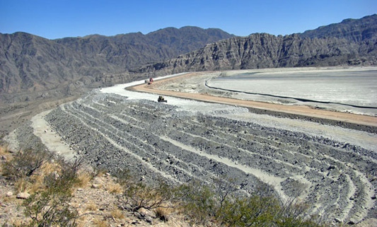
Figure 1: Modified centreline raise of an tailings storage facility (© Jon Engels)
Introduction
A conventional impoundment is a surface retaining structure designed to store both tailings and mine water, with the aim of reclaiming the water for use in the processing plant as required. There are principally two types of surface impoundments, a water retention type dam, and a raised embankment that has many configurations (Vick 1990). The main difference is that a water retention dam is constructed to its full height before any discharge to the impoundment (EPA 1994). Raised embankment dams are built higher as the requirement to store more tailings and process/storm water becomes apparent.
Water Retention
Water retention dams for tailings differ only slightly from conventional water storage structures. The principal designs and construction techniques are the same, the main difference being that tailings storage embankments have a steeper upstream slope as they do not need to be engineered to cope with the rapid drawdown that is experienced in a conventional water retaining structure (Vick 1990).
Water retention tailings dams are mainly used for mineral operations that plan to store high volumes of water. Water storage may be required to keep a processing plant operational during the dry season or where surface water inundation can occur especially if the impoundment is in a catchment area.
Raised embankment designs
The raised embankment design is the most common construction technique used in tailings storage facilities. The three principal designs are downstream, upstream and centreline structures, which designate the direction in which the embankment crest moves in relation to the starter dyke at the base of the embankment wall (Vick 1990). Modified centreline is another method rarely used which is a combination between upstream and centreline construction.
As the name suggests the embankment is raised at certain time intervals to increase the available volume for the storage of tailings and water, thus they have a lower initial capital cost than retention dams because fill material and placement costs are phased over the life of the impoundment. The choices available for construction material are increased as smaller quantities are needed at any one time. For example, retention dams generally use natural soil whereas raised embankments can use natural soil, tailings, and waste rock in any combination (Vick 1990). The most common materials used for embankment raises are waste mine rock, natural borrow soils, underground roadway development material, cycloned tailings (coarse fraction) and hydraulically deposited tailings. With the developments of high capacity earthmoving equipment in the 1940’s raises can be compacted in a similar manner to that of water retention dam construction techniques (Martin, Davies et al. 2002). Today, raised embankment construction is almost always mechanised to gain the level of compaction required to increase the safety and lower the risk of instability of the storage facility.
Upstream
The upstream method is the lowest initial cost and most popular design for a raised tailings embankment in low risk seismic areas. One of the reasons for this is mainly due to the minimal amount of fill material required for initial construction and subsequent raising which normally consists entirely of the coarse fraction of the tailings.
The construction of an upstream designed embankment starts with a pervious (free draining) starter dyke foundation. The tailings are usually discharged from the top of the dam crest creating a beach that becomes the foundation for future embankment raises (Vick 1990). Figure 2 shows a simplistic diagram of the stages of construction of an upstream raised embankment. Where the tailings properties are suitable, natural segregation of coarse material settles closest to the spigot and the fines furthest away (not always the case with thickened tailings discharge). Cyclones can be used to accelerate this particle segregation for certain tailings characteristics to send the slime proportion to the centre of the impoundment and the sand fraction to the beach behind the crest. The conventional method of upstream raises relies on no compaction of the spigotted beach that forms the embankment shell (Martin 1999). Today compaction by earthmoving equipment is common to increase the degree of safety of raised embankments. Generally the settled coarse fraction from the spigots/discharge point is used as the raise material for the embankments. For multiple spigot discharge a series of shallow pits are dug in front of the spigots (once the tailings have dried and consolidated) and tailings placed on the embankment crest, then they are compressed, the tailings lines lifted and reassembled then normal operation commences.
It is not surprising that the upstream method is the most common design to fail causing huge environmental consequences all over the world (ICOLD and UNEP 2001). Davies et al. (2000) note that there are reported to be just over 3500 tailings dams worldwide of which 50% are of the upstream design. It was also noted that the key failure mode of upstream embankments is a static/transient load induced liquefaction flowslide event. This is not surprising considering the low relative density of the tailings and the potential for water mismanagement to generate high saturation of the embankment and subsequently creating liquefaction induced flows of the tailings.
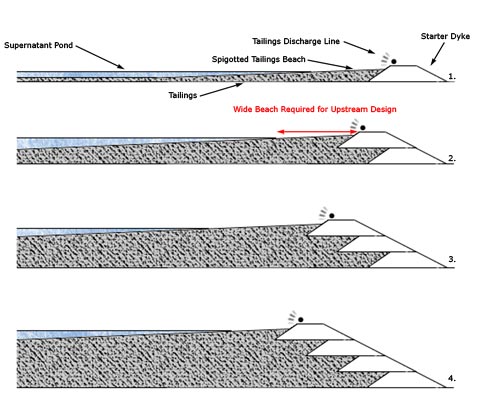
Figure 2: Upstream method of embankment construction (© Jon Engels)
This coarse beach material is essential for upstream designed impoundments to aid drainage and prevent saturation of the embankments. This allows for a stronger and more permeable crest to develop which reduces the height of the phreatic surface as the embankment progressively rises. The best way to reduce the phreatic surface is to have a wide Beach Above Water (BAW) between the dam crest and the supernatant pond (free water) within the impoundment (Shaheen, Martin et al. 2003). The closer the supernatant pond is to the dam crest, the higher the phreatic surface of the embankment and thus the greater the risk of failure. The filter under-drain system of the embankments is a key component in reducing the phreatic surface of an upstream designed embankment (ICOLD and UNEP 2001).
Upstream embankments are suited to areas where the climate is arid, minimal amounts of water require storage in the impoundment and rapid water accumulation is improbable (e.g. upstream water inundation and flooding). This helps to promote wide beaches and prevent frequent water level deviations that can dramatically alter pond geometry, freeboard and the phreatic surface within the impoundment area. Upstream embankments are not suited to areas of seismic activity as the risk of liquefaction increases as a result of the potential for dynamic loading by earthquakes. In some countries, for example Chile, upstream construction is not permitted for this reason.
Rates of rise of upstream embankments have to be controlled to prevent increased pore pressures that can reduce the shear strength of the fill material (Jakubick, McKenna et al. 2003). Excessive rates of rise have been a trigger for static liquefaction that has been the underlying cause for many upstream tailings impoundment failures (Davies, McRoberts et al. 2002).
Downstream
The downstream design was developed to reduce the risks associated with the upstream design, particularly when subjected to dynamic loading as a result of earthquake shaking (ICOLD and UNEP 2001). The installation of impervious cores and drainage zones can also allow the impoundment to hold a substantial volume of water directly against the upstream face of the embankment without jeopardising stability.
The downstream embankment design starts with an impervious starter dyke unlike the upstream design that has a pervious starter dyke. The tailings are at first deposited behind the dyke and as the embankment is raised the new wall is constructed and supported on top of the downstream slope of the previous section (figure 3). This shifts the centreline of the top of the dam downstream as the embankment stages are progressively raised (Vick 1990). An advantage to the downstream design is that the raised sections can be designed to be of variable porosity to tackle any problems with the phreatic surface of the embankment. This can be particularly useful where a processing plant has made changes to increase efficiency and as a result alter the tailings characteristics. This may result in pumping more water to the tailings facility or alter the drainage characteristics of the newly deposited tailings.
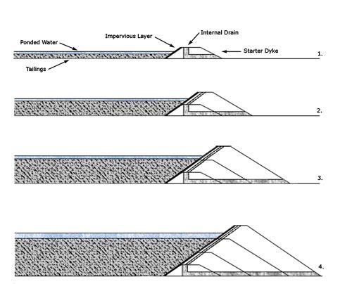
Figure 3: Downstream method of embankment construction (© Jon Engels)
The downstream design is very versatile for a range of site specific design parameters and behaves similarly to water retention dams. Their main advantage is that the downstream design can have unrestricted heights due to each raise being structurally independent of the tailings. The main disadvantage is the cost of raising the embankment as large volumes of fill are required which increases exponentially as embankment height increases, and subsequently a large area around the dam itself is required as the toe of the dam moves out as more raises are added. This can cause problems where limited space has been taken into consideration prior to building, or if property line and utilities are in close proximity. Although a downstream embankment can theoretically have no height limit, the dam’s ultimate height is determined by the restriction of the advancing toe (Vick 1990).
Centreline
The centreline method is really a compromise between both the upstream and downstream designs (Benckert and Eurenius 2001). It is more stable than the upstream method but does not require as much construction material as the downstream design. Like the upstream method the tailings are generally discharged by spigots from the embankment crest to form a beach behind the dam wall. When subsequent raising is required, material is placed on both the tailings and the existing embankment. The embankment crest is being raised vertically and does not move in relation to the upstream and downstream directions of subsequent raises, hence the term, centreline design (figure 4).
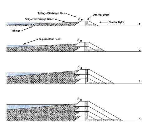
Figure 4: Centreline method of embankment construction (© Jon Engels)
The design incorporates the internal drainage zones that are similarly found in the downstream method. Therefore, the free water can encroach closer to the dam crest than the upstream method without the worry of increasing the phreatic surface and causing a potential failure risk. However, a centreline dam cannot be used as a large water retention facility solely due to the subsequent raises being partially built on consolidated tailings. A suitable decant system needs to be installed to prevent the free water submerging the beach around the dam crest.
In many cases the centreline design is a good compromise between the seismic risk and the costs associated with construction (EC 2004).
Modifed Centreline
Modified centreline is a compromise between the upstream and centreline methods to reduce the volume of construction material placed in the downstream shell of the embankment. The angle of the upstream crest advance over the tailings is calculated during the design phase following stability and seepage analyses. Rockfill is usually utilised in this technique to gain a higher angle, rather than the coarse tailings fraction to reduce risk of instability.
In countries where upstream construction is not permitted (i.e. due to seismic risk), the modified centreline method may also not be permitted due to the concept of partially placing construction material on the existing tailings beach.