Deposition Methods of Tailings
Deposition Methods of Tailings
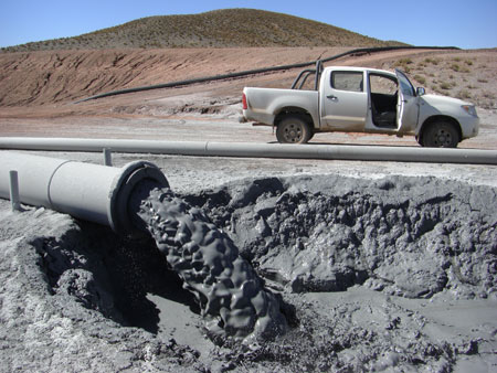
Figure 1: Single point discharge of tailings (Subaerial technique) (© Jon Engels)
Introduction
For conventional storage the tailings are generally discharged from spigots/outfalls located along the embankment(s) of the facility. For surface thickened and paste storage the tailings are generally discharged from a central location either through risers or from point sources that are raised over the life of the facility. Dry stacking of tailings is normally carried out by a radial conveyor stacker or by truck (Davies and Rice 2001).
Deposition techniques
Tailings can be discharged using subaqueous (below water) or subaerial techniques (above the water line, on the ground or on the tailings beach) (DPI 2003). The choice between these methods can dramatically effect how the tailings deposit and settle within the impoundment. The tailings characteristics themselves can also influence the behaviour of the tailings after they are discharged. Generally as the tailings deposit they flow away from an outfall and natural segregation occurs. The degree of this segregation essentially depends on the particle size range of the tailings and the pulp density of the slurry (Vick 1990). Robinsky (2000) reported that as the degree of thickening of tailings increases there is less slurry to carry the coarse fraction and the tailings begin to stack closer to the discharge point increasing the tailings beach slope. Further thickening eventually results in a non-segregated slurry due to the high pulp density of the depositing tailings. When this stage is reached the voids in the coarse fraction of the slurry are filled with the fines resulting in a homogeneous mixture. This is a common characteristic associated with paste tailings.
For low pulp densities the coarse fraction of the tailings generally settle closest to the discharge point with the finer material (slimes) being carried furthest away. The deposition flow rate from the spigot greatly influences this segregation or if flows from adjacent spigots combine as a single stream further down the beach. For subaerial deposition this results in a beach sloping downwards from the spigot towards the supernatant pond. Vick (1990) notes that for most tailings types the expected beach slope grade is 0.5 – 2.0% within the first several hundred feet and that the higher the pulp density and/or the coarser the gradation of the tailings the steeper the beach slope. Concavity in the beach between the discharge point and the supernatant pond is common and a function of material segregation and tailings velocity variations as they flow down the beach. See the beach slope section for more information.
Multiple outfall deposition (spigots) is the most common method used to fill a surface storage facility. For conventional storage facilities, multiple spigots help to control the geometry and location of the supernatant pond within the facility. This helps to prevent the pond encroaching the embankment and reduces the risk of loss of freeboard. Static single point discharge is normally only used when the ponded water is pushed to a required zone of the tailings facility or where subaqueous deposition is practiced.
Multiple spigoting also has the advantage to control the layer thickness of tailings. It is common to use a cyclic program of discharge and drying of zones within a tailings facility to promote in situ density gain and thus optimise storage volume available.
Subaerial
Subaerial deposition is more common than subaqueous as it can form a Beach Above Water (BAW) sloping gently towards the supernatant pond (figure 2). As the tailings discharge onto this beach they form shallow low velocity braided streams that allow the tailings to settle and segregate (DME 1999). Subaerial deposition is generally practiced at tailings facilities that have multiple discharge points. This allows the deposition of tailings to be rotated between different locations around the facility to allow newly deposited tailings to bleed, dry and consolidate while tailings can continue to be discharged to other zones of the facility. The frequency of discharge point rotation and the number of deposition zones is dependent on the climate, tailings production rate, tailings drying characteristics and the tailings facility shape (Gipson 1998).
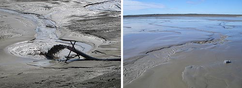
Figure 2: Subaerial tailings discharge (left) and shallow low velocity braided streams on a tailings beach (right) (© Jon Engels)
The general process of multiple subaerial deposition is as follows (modified from (Ulrich, East et al. 2000)):
Subaerial deposition exposes the beached tailings to oxygen and water allowing oxidation of infused sulphides and the production of acids (Newman, White et al. 2001), where the tailings have acid generation potential. However, the exposure of tailings can maximise evaporation and can help to degrade cyanide compounds if they have been used in the ore extraction process (DPI 2003).
Subaqueous
Subaqueous deposition is particularly suited to tailings that contain sulphides that are likely to oxidise, mobilise metals and produce acid (Tremblay 1998). Restricting oxygen to the tailings by permanently placing them underwater will prevent oxidation and minimise the environmental problems associated with Acid Mine Drainage (AMD) (figure 3). With this in mind, the offshore disposal of tailings to natural water bodies is appealing but the actual overall environmental consequences of this technique are not fully understood. However, subaqueous deposition can be practiced in conventional impoundments.
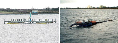
Figure 3: Subaqueous deposition within a conventional tailings impoundment (Courtesy Anglo American) (© Jon Engels)
The Lisheen mine in Ireland is one such site that uses this technique to control AMD. Part of their license to operate requires them to deposit all their tailings subaqueously with a minimum water depth of 1.3 m above the tailings in June and 1 m in October (EPA 2000). As a result the Tailings Management Facility (TMF) stores a considerable volume of water right up to the upstream faces of the embankments. The tailings are discharged from a mechanised floating head that is controlled by two railtrack mounted trucks on either side of the impoundment. The TMF is fully lined on the upstream embankment face with a composite linear low density polyethylene (LLDPE) liner and a geosynthetic clay liner (GCL). The basin area is lined with LLDPE and the compressed peat underneath acts as a second lining (Dillon, White et al. 2004).
Discharging of tailings below water can create significantly steeper slopes than that of subaerial deposition (Robertson and Wels 1999). Dillon et al. (2004) report that for Lisheen the underwater tailings slope could be in excess of 10%. This means that if the distribution head or spigot is not regularly moved then differential settlement, slumping and squeezing can occur. This can damage synthetic liners particularly if the underlying material is likely to compress. It is essential for a lined impoundment using subaqueous deposition that the tailings are evenly distributed and that depth measurements are recorded at regular time intervals to establish dramatic elevation changes.
Spigots
Spigot disposal (normally subaerial) is used where the tailings are discharged generally around the perimeter of the tailings facility (ring dyke construction) to create a beach between the embankment and the supernatant pond (Ritcey 1989). This generally means the pond is completely surrounded by beached tailings (figure 4). The spigots are changed over as set out by the deposition plan to promote bleeding and drying prior to further layering and raising. It is essential that a deposition plan be established during the design stage and implemented and managed throughout the operational stage.
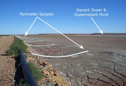
Figure 4: Multiple spigot discharge at the Jundee Gold Mine, NT, Australia (© Jon Engels)
The ideal spigot spacing can be determined by deposition trials to establish likely beach slope angles and widths. Incorrect spacing can lead to undulating beaches between spigots that can ultimately reduce the efficiency of tailings deposition.
Multiple spigoting creates pipework management challenges as blockages and ruptures can occur (DPI 2003). Monitoring and maintenance schedules are also intensified to ensure that tailings are being delivered to the correct areas, for the correct time period and in the intended quantities. Normally multiple spigots are small diameter pipes that feed off ring main configurations (sometimes known as distribution lines) that then feed off the larger diameter main delivery lines from the plant. The pipeline size reduction ratios and incorrect flow velocities can lead to sanding and plugging of lines (WMC 1998). Valve stations and flushing lines are also required for multiple spigots to allow lines to be flushed to prevent sanding after they have been shutdown.
Multiple spigotting helps to reduce the discharge velocity of the tailings being pumped to the storage facility compared to single point deposition. This helps to promote laminar rather than turbulent flow allowing the coarse particles to settle nearer the spigot creating a greater drainage potential. This will also promote a slightly steeper angled beach that will aid the removal of fluids from tailings deposited near the spigot (Ulrich, East et al. 2000).
Single point
Single point discharge requires irregular movement of the discharge lines. Vick (1990) reports that deltas are normally formed or a single beach deposit of tailings within the impoundment (figure 5). This normally means the supernatant pond is restrained to a certain area of the impoundment which may be against one of the embankment walls resulting in high and low ends of the impoundment. The lower end of the impoundment will collect the slimes increasing the possibility of seepage erosion (Ritcey 1989). This type of deposition is not suitable where the pond and/or the slimes must be kept away from an embankment (EPA 1994).
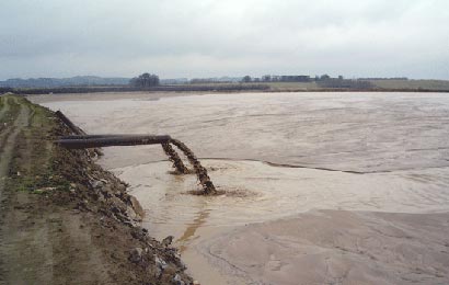
Figure 5: Single point discharge at Glebe Mines, Derbyshire, England (© Jon Engels)
Single point deposition can place the tailings in fairly thick layers causing the tailings to remain saturated for years if not dried before new layers are deposited (Norman 1998). This method of deposition is suited to valley type impoundments (downstream and some centreline embankment designs) where the supernatant pond can be forced to reside against a valley face (i.e. against the hillside away from the retaining embankments).